On this page you’ll find wiring instructions for creating a referee light system that adheres to the rules of the International Powerlifting Federation. Anyone with some electromechanical knowledge can create this. There is no need to learn micro-controller/Arduino programming as you can just use our code.
Our solution is wired. If you’re looking for a complete wireless solution, I suggest you check out Ben Sanda’s project on Github.
Prerequisites
- Arduino/Genuino Uno Microcontroller. An official one.
- Power Adapter for the Arduino
See the requirements at Arduino. We chose this one. - Relays
We wanted the lights to be compatible with 220 volts and found these four and two relays. - Buzzer
We found one that produces 400 Hz at 90 dB. This is the lowest tone we could find at 5 volts (the Arduino outputs 5 volts). - The rest is quite straight forward: light bulbs and sockets (we use LED and E27), some jumper/breadboard cables, cables (2×10 metres and 1×15 meter), referee switches (we use two way rotary switches that automatically return) et cetera.
At first we wanted a LED Signal Tower as this is highly visible from every angle, but this turned out to be too expensive.
IPF Rules
“A system of lights shall be provided whereby the referees make known their decisions. A system of lights similar to those used in weightlifting may be used, whereby when a referee detects an infraction he activates his control. If a majority activates their control a buzzer sounds and the lifter knows that his lift has failed. He is not then required to finish the attempt. Each referee will control a white and a red light. These two colours represent a “good lift” and “no lift” respectively. The lights shall be arranged horizontally to correspond with the positions of the three referees. They must be wired in such a way that they light up together and not separately when activated by the three referees.” – IPF Technical Rules 2015
Configuring the Arduino
Notes:
- Following the IPF rules literally two referees choosing “no lift” activates our buzzer. However, since the Arduino can only do one thing at a time, the third referee can not declare a judgment during that time.
The buzzer time is configurable and we chose 700 ms. We always ask the referees to hold the switch for 1 second and found that this does not trouble them.
If you only want the buzzer after all three referees made a choice, just set “buzzimmediately” to “0” in the script. We currently also do this in the Netherlands. - We output the referee choices through serial communication via USB to a computer. We plan to use this for our meet management software.
Wiring schedule
Connect the following wires to the following points on the controller:
- In the drawing only one button and one relay wiring is shown. The other 5 have to be done the same way.
- The pins you use can be configured in the script.
- For the switches we used pull-down resistors as shown on the Arduino site.
- Our relays fire up the lights when receiving a LOW output from the Arduino. We use the function lightmode() to invert the HIGH input from the buttons into a LOW output for the relays. If you don’t need this, remove lightmode(***) in void lights() (leave what’s inside the brackets).

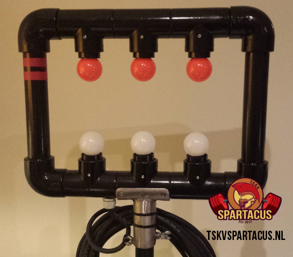
The result
We used a construction of PVC pipes which we put on top of a speaker stand. It’s light-weight, allows watching from a very large angle and light bulbs are easy to change. Besides that, we are also working on additional software-based lights.
You can also view the lights in action in our photoalbums at our Facebook page.
F.A.Q.
Do you sell your Electronic Referee Light Systems?
No.
What would you do different if you would do it again?
- Use the built-in pulldown resistors of the Arduino.
- Perhaps allow for parallel activities by adding another board for the buzzer or try to use a Raspberry Pi.
- Hook up a stadium sports buzzer.
- If I had to do it cheap and wireless, I’d use a Raspberry Pi with 3 wireless mouses and a tv-screen to show “the lights” (code starter). Or do it all through a webinterface and give the referees iPods/tablets/mobile phones.
- Also create a blue and yellow button to incorporate the failure reason. Due to cost reasons we chose not to. Even more, it could delay the referee’s choice.